


 English
  中文简体
中文简体 Recently, as safety requirements for global power and communications infrastruct...
Read More

Home · News · Industry News · How Does a Ground Work? Key Components and Exothermic Connections for Safety
Industry News
How Does a Ground Work? Key Components and Exothermic Connections for Safety
2026-09-17Content
An electrical grounding system works by creating a dedicated, low-impedance path that carries fault currents, lightning surges, and static charges safely into the earth. Without it, metal enclosures, equipment frames, and structural steel could become energized, posing lethal shock hazards and fire risks. A ground that truly works relies on three interdependent elements: a conductive electrode buried in the soil, a network of conductors that carry the current, and joints that remain stable for decades. The weakest link in any of these parts compromises the entire system.
The Ground Electrode – Where the System Meets Earth
The electrode is the physical interface between the grounding circuit and the soil. Its performance depends on material corrosion resistance, contact surface area, and soil resistivity. Two common choices are copper‑clad steel rods and hot‑dip galvanized steel rods.
| Material | Corrosion Resistance | Typical Lifespan (years) | Best‑suited Soil Type |
|---|---|---|---|
| Copper‑clad steel rod | Excellent | 30–40 | Acidic, high‑salt, or moist |
| Hot‑dip galvanized steel rod | Good | 15–25 | Neutral, low‑corrosive |
| Solid copper rod | Excellent | 50+ | Any, but higher cost |
Copper‑clad steel rods combine the conductivity of copper with the mechanical strength of steel, making them the most widely specified electrode for substations, transmission towers, and commercial buildings. 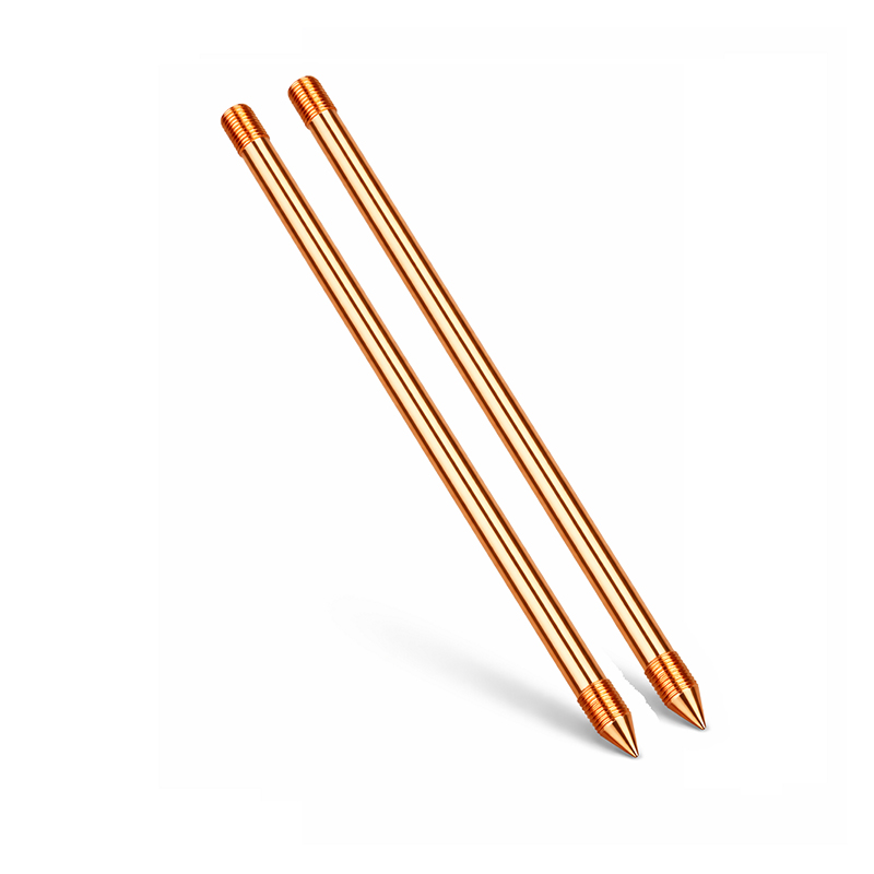 Copper-Clad Steel Ground Rod for Stable ResistanceThis rod combines copper conductivity with steel strength, resisting corrosion in aggressive soil. It provides the low-resistance interface required before connecting conductors to equipment grounds and lightning terminals.View Product →The rod’s outer copper layer resists corrosion even when the soil pH is aggressive. When driven to the required depth (typically 2.4 m or more), it delivers a stable ground resistance. For projects requiring a longer service life in highly corrosive environments, solid copper rods or copper‑clad rods with thicker plating are preferred, though at a higher material cost.
Ground Conductors – Carrying the Current to Earth
Once the electrode provides the low‑resistance interface, a conductor must connect every equipment ground bus, structural steel member, and lightning air terminal to that electrode. The conductor must handle the full fault current without fusing or overheating, and its connections must remain mechanically and electrically stable.
Common conductor types and their roles
- Bare hard‑drawn copper stranded wire – The standard choice for buried grounding grids and above‑ground bonding. Its high conductivity and mechanical strength resist breakage during installation.
- Copper‑clad steel stranded wire – Used where a combination of strength and corrosion resistance is needed, such as long spans in grounding grids or connections to remote electrodes.
- Copper flat bar and busbar – Preferred for equipment grounding inside switchgear rooms and for bonding multiple cables to a common point.
- Hot‑dip galvanized steel flat bar – Economical option for large grounding grids in non‑corrosive soils, often paired with exothermic welded joints.
Bare hard‑drawn copper stranded wire is the industry standard for direct‑burial grounding conductors. 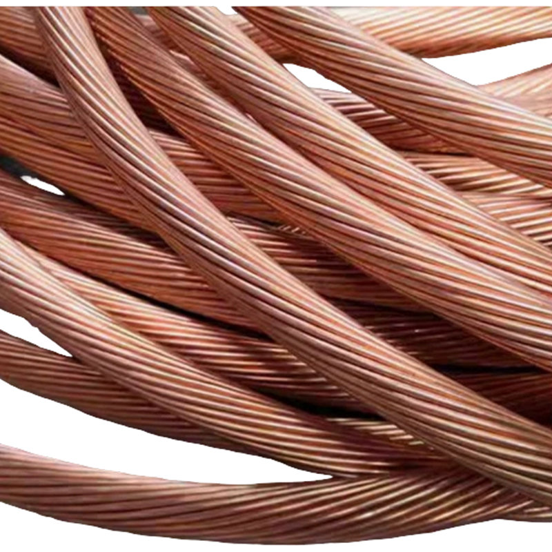 Bare Hard Copper Stranded Wire for Direct BurialMade of ≥99.9% pure copper, this stranded wire offers low resistance and flexibility for trench installation. Its reliable connection to electrodes is critical; exothermic welding ensures a permanent metallurgical bond that mechanical clamps cannot match.View Product →Its purity (≥99.9 % copper) ensures minimum resistance, and the stranded construction provides flexibility to follow trench contours. For applications where the conductor must also resist theft – common in remote tower sites – copper‑clad steel stranded wire offers a practical alternative with lower scrap value.
Joints – Where Most Grounding Failures Occur
The connection between the conductor and the electrode, and between conductor segments, is the most failure‑prone part of any grounding system. Mechanical clamps and lugs rely on surface‑to‑surface contact that can loosen over time due to thermal cycling and corrosion. Exothermic welding eliminates these failure modes by forming a true metallurgical bond between the conductor and the electrode.
How exothermic welding works
A copper‑based exothermic reaction takes place inside a graphite mold. The molten copper flows around the conductors and into the mold cavity, fusing with the base metals at the atomic level. The result is a permanent joint with ampacity equal to or greater than that of the conductor itself. There is no mechanical interface to degrade, no added resistance at the connection, and no need for periodic re‑torquing.
| Joint Type | Initial Contact Resistance (µΩ) | Resistance After 5 Years (µΩ) | Failures per 1,000 Joints |
|---|---|---|---|
| Exothermic welded | 2–5 | 2–6 | < 0.1 |
| Compression lug (tin‑plated copper) | 8–15 | 15–40 | 2–5 |
| Bolted clamp (galvanized steel) | 20–60 | 50–120 | 5–10 |
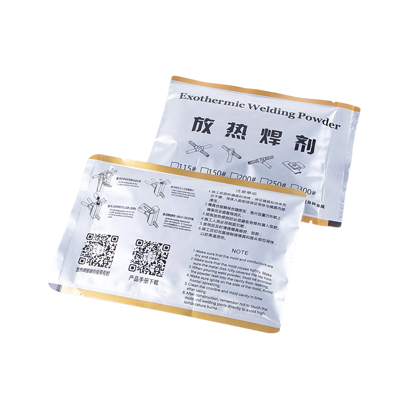 Exothermic Welding Powder for Permanent Ground JointsThis powder produces a high-temperature reaction that forms a conductive, porous-free metallurgical bond. It eliminates corrosion and loosening risks in grounding joints, ensuring consistent low impedance essential for protective relay coordination and lightning safety.View Product →For permanent grounding grid connections, exothermic welding is not a preference – it is a reliability requirement. The process is independent of external power sources, making it suitable for remote tower foundations and trench work. The exothermic welding powder used must meet the correct particle size and chemical composition to produce consistent, porous‑free joints. Each weld should be inspected visually and with a resistance test before backfilling.
The impact of a poor joint can be severe. A bolted connection that corrodes to a resistance of 100 µΩ instead of the design value can cause the ground impedance to rise above the threshold required for protective relay coordination. During a lightning strike, the high impedance results in elevated ground potential rise, potentially damaging equipment and endangering personnel. Exothermic welding directly eliminates this risk by ensuring every joint remains as conductive as the conductor itself.
Lightning Air Terminal – The Top End of the Ground
A grounding system without a properly designed air terminal (lightning rod) cannot protect a structure from direct lightning strikes. The air terminal intercepts the upward leader and conducts the lightning current down to the grounding electrode. Modern early‑streamer emission and advanced discharge rods extend the protection zone, allowing fewer terminals to cover larger roof areas. Regardless of the terminal design, the connection from the air terminal to the down conductor and from the down conductor to the ground grid must be exothermic welded to handle the multi‑kiloampere current without flashing or mechanical failure.
Putting It All Together – How a Ground Actually Works
A ground that works is a complete, closed circuit from the point of fault or lightning strike, through a conductor of sufficient cross‑section, through a permanent metallurgical joint, into an electrode with adequate surface area and low soil resistivity. No single component can compensate for a deficiency in another. Selecting the right rod material, the correct conductor type, and the most reliable joining method – exothermic welding – ensures the system will perform its safety function for the entire life of the installation. For engineers and procurement teams evaluating grounding materials, the decision criteria should prioritize long‑term stability over initial cost. A system built with galvanized steel rods, compression lugs, and generic grounding clamps may pass an initial site test, but corrosion and thermal cycling will degrade its performance within a few years. In contrast, a system using copper‑clad steel rods, bare copper stranded wire, and exothermic welded connections will maintain its designed impedance for decades, reducing maintenance costs and preventing safety incidents.
PREV: No previous article
NEXT: How Lightning Rods Work: What Affects Their Effectiveness and Safe Grounding
Contact Us
Your email address will not be published. Required field are marked*
News
-
-
Exothermic welding powder plays a crucial role in creating strong and reliable e...
Read More -
Exothermic welding is a process that fuses two metal conductors into a single m...
Read More -
An air terminal by itself does not protect a building. A lightning rod works on...
Read More -
Recently, as global requirements for power safety and lightning protection groun...
Read More -
Copper-Clad Steel Rod: Definition and Manufacturing Process Analysis What is a C...
Read More

The company is committed to in-depth research in the field of
grounding and large-scale manufacturing of products. It is a
comprehensive technology enterprise integrating R&D,
manufacturing and technical services. It is a high-quality
supplier for many domestic first-line engineering construction
companies.
- Contact Information
-
- TEL
- +86-575 8930 2616
- +86-130 6788 7328
- Address
- No. 55, Gaoxiang Road, Shengzhou City, Shaoxing City, Zhejiang Province, China
- Grace Wang
- E-mail: [email protected]
- Phone:+86 135 8735 6239
- WhatApp: +86 135 8735 6239
- WeChat: +86 135 8735 6239
- Lucy Xu
- E-mail: [email protected]
- Phone:+86 139 0585 3744
- WhatApp: +86 139 0585 3744
- WeChat: +86 139 0585 3744
- April Zhang
- E-mail: [email protected]
- Phone:+86 139 0585 4994
- WhatApp: +86 139 0585 4994
- WeChat: +86 139 0585 4994

