


 English
  中文简体
中文简体 How does grounding work? Set the jargon aside and it comes down to one simple i...
Read More

Home · News · Industry News · How Does Electrical Ground Work? A Practical Guide to Grounding Systems
Industry News
How Does Electrical Ground Work? A Practical Guide to Grounding Systems
2026-09-21Content
Every building, substation and telecom tower quietly depends on metal buried in the dirt. Nobody sees it and nobody plugs into it, yet the moment something goes wrong with an electrical system, that hidden metal becomes the most important conductor on the site. Working around ground rods, copper conductors and welding molds day after day, we still hear the same refreshingly honest question from engineers and procurement teams alike: how does electrical ground work? Here is the plain-language explanation we share on job sites, true to the physics but stripped of jargon.
What "Ground" Actually Means in an Electrical System
When electricians say "ground," they mean two things at once. The first is literal: the soil of the earth itself, treated as a universal reference point sitting at zero volts. The second is the deliberate connection we build between an electrical system and that soil — a network of electrodes, conductors and bonds designed so that electricity always has a safe way home.
The earth can serve as that reference because of sheer scale. Push a charge into the ground and it spreads through an effectively unlimited volume, the way a kettle of hot water disappears into the ocean. No matter how much fault current or lightning energy arrives, the overall potential of the earth barely moves, and that stability is what lets every voltage in a system be measured against it.
One point is worth clearing up early: the ground conductor is not part of everyday current flow. Under normal conditions it sits completely idle. It is an emergency lane, reserved for the moments when current ends up somewhere it should never be.
How Grounding Works, Step by Step
The clearest way to understand grounding is to follow a fault from start to finish.
- Under normal operation, current leaves the source through the hot conductor, passes through the load, and returns on the neutral. The grounding conductor carries nothing.
- A fault occurs — insulation ages, a wire chafes, and the hot conductor touches a metal enclosure.
- Because that enclosure is bonded to the grounding system, the casing instantly becomes part of a very low-resistance loop back to the source.
- Fault current surges through the loop, and the protective device — a breaker or fuse — trips within milliseconds.
- Any current that continues into the earth spreads through the soil around the electrode and dissipates harmlessly.
Two details make this work. First, current always prefers the path of least resistance, so a well-built ground path keeps fault current away from human bodies and flammable materials. Second, the same logic applies to lightning and switching surges: a low-impedance path to earth gives that energy somewhere to go other than through wiring, electronics or people.
There is a common misconception that soil is a wonderful conductor. Meter for meter, it is not — dry, rocky ground can be remarkably resistive. Grounding works because an electrode gives current an enormous cross-section of earth to spread into. That is why electrode design matters so much: the material, the driven depth, the number of rods and the resistivity of the surrounding soil all decide how low the final resistance lands.
The Anatomy of a Grounding System
From a single residential rod to a substation grid, every installation is assembled from the same three families of components.
The electrode: where current meets soil
The electrode is the buried element that actually transfers current into the earth. Driven ground rods remain the workhorse because they reach stable moisture and temperature at depth. Material choice is a balancing act: pure copper offers the best conductivity and corrosion resistance but is soft and costly; copper-clad steel pairs a conductive copper surface with a steel core strong enough to survive being driven; hot-dip galvanized steel keeps large grids affordable. If you are weighing these options, our grounding material selection guide walks through the trade-offs in detail.
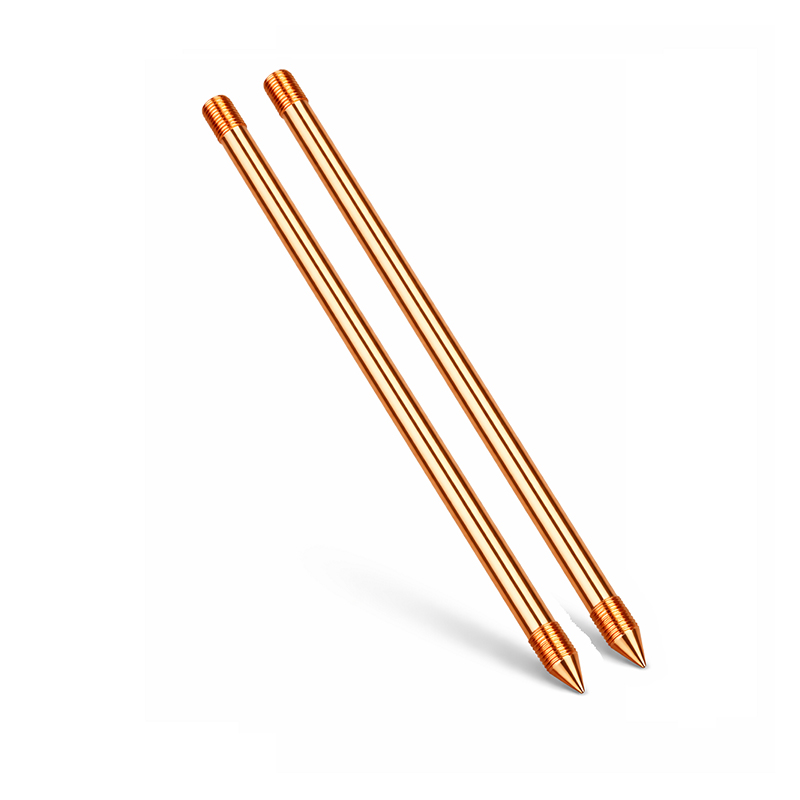 Copper-Clad Steel Grounding RodWith a conductive copper layer over a strong steel core, these rods combine conductivity with the tensile strength needed for driving. They suit buried electrodes where stable grounding and corrosion resistance matter.View Product →
The conductors: carrying current to the electrode
Stranded copper does most of the hauling above ground. Hard-drawn copper stranded wire suits fixed runs such as down-conductors; flexible copper stranded wire handles bonding jumpers and equipment connections; PVC-covered or tin-plated versions add protection where moisture, corrosion or contact with other metals is expected. Copper flat bar and tape appear wherever a compact, high-capacity path is needed, such as ring conductors and equipotential ties.
The connections and clamps: holding it all together
Between electrodes and conductors sits the hardware: U-type and V-type clamps that fasten conductors to rods, cable lugs that land wires on busbars, and accessible earth pits that let inspectors check joints years later without excavation.
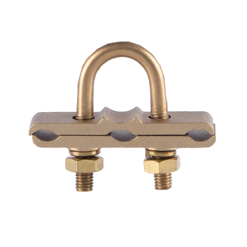 U-Type Ground ClampThis clamp secures conductors to ground rods with stable electrical contact, corrosion resistance, and easy installation. It is the essential fastening hardware between buried electrodes and above-ground conductors.View Product →
| Material | Conductivity | Corrosion Resistance | Mechanical Strength | Typical Role |
|---|---|---|---|---|
| Pure copper | Excellent | Excellent | Soft | Busbars, tape, premium electrodes |
| Copper-clad steel | Very good | Very good | High | Driven ground rods, down-conductors |
| Hot-dip galvanized steel | Moderate | Good | High | Economical grids, structural earthing |
Why the Connection Is the Weakest Link — and How Exothermic Welding Fixes It
Ask anyone who maintains grounding systems where failures actually happen, and the answer is rarely the rod or the wire. It is the joint. Mechanical connections loosen as conductors expand and contract with temperature, corrode where dissimilar metals touch, and quietly accumulate resistance year after year — until a fault or a lightning strike finds the gap.
Exothermic welding takes a different approach. A powdered mixture of copper oxide and aluminum is loaded into a graphite mold together with the conductors being joined. Once ignited, the reaction produces molten copper at around 2,500 degrees Celsius, fusing the conductors into a single solid piece. The finished joint behaves like a cast copper connector: it cannot loosen, it resists corrosion, and it carries current at the full rating of the conductor itself. That is why permanent bonds — a copper tape to a ground rod, or several conductors converging on one electrode — are specified by default in substations, rail networks and telecom sites. For a closer look at the chemistry, we explain how exothermic welding powder enhances electrical connections in a separate article.
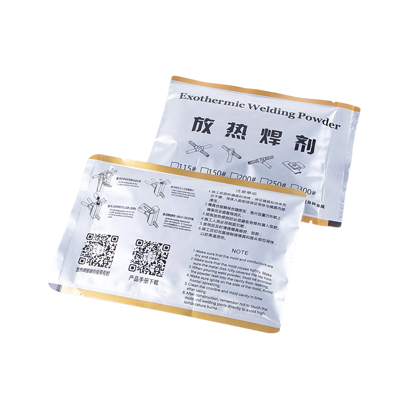 Exothermic Welding PowderIgnited in a graphite mold, this powder produces molten copper that fuses conductors into permanent, corrosion-resistant joints. It addresses the connection failures that mechanical clamps gradually develop.View Product →
Grounding in the Real World
The same principles scale from a garden-wall outlet to a switching yard:
- Homes: the third prong on an outlet ties appliance casings to the ground bar in the service panel, which connects back to a rod outside — so a fault in a washing machine trips the breaker instead of shocking the user.
- Substations: a buried copper grid equalizes potential across the yard, keeping step and touch voltage within safe limits during a fault.
- Telecom towers and buildings: an air terminal up top intercepts the strike, down-conductors channel the energy, and the electrode array disperses it — one continuous, bonded path from sky to soil.
- Industrial plants and pipelines: bonding jumpers maintain equal potential between structures, while earth pits give inspectors access to test joints without excavation.
Whatever the scale, the recipe is identical: a stable electrode, a conductor sized for the expected current, and connections you can trust for decades.
So, how does electrical ground work? It gives electricity a stable zero-volt reference, an emergency path that lets protective devices trip in milliseconds, and a drain that turns lightning energy into warmth scattered through the soil. None of it is glamorous, and all of it depends on every component — the rod, the conductor and above all the connection — staying conductive for the life of the installation. That is the standard we hold our grounding materials to, and if you are specifying a system right now, we are always glad to talk through the details.
PREV: How Does a Lightning Rod Work? A Practical Guide to Complete Protection
NEXT: How Does a Ground Work? Key Components and Exothermic Connections for Safety
Contact Us
Your email address will not be published. Required field are marked*
Categories
- Company News(1)
- Industry News(19)
News
-
-
“How does a lightning rod work?” is one of those questions that sounds simple u...
Read More -
An air terminal by itself does not protect a building. A lightning rod works on...
Read More -
Copper-Clad Steel Rod: Definition and Manufacturing Process Analysis What is a C...
Read More -
An electrical grounding system works by creating a dedicated, low-impedance pat...
Read More -
Exothermic welding is a process that fuses two metal conductors into a single m...
Read More

The company is committed to in-depth research in the field of
grounding and large-scale manufacturing of products. It is a
comprehensive technology enterprise integrating R&D,
manufacturing and technical services. It is a high-quality
supplier for many domestic first-line engineering construction
companies.
- Contact Information
-
- TEL
- +86-575 8930 2616
- +86-130 6788 7328
- Address
- No. 55, Gaoxiang Road, Shengzhou City, Shaoxing City, Zhejiang Province, China
- Grace Wang
- E-mail: [email protected]
- Phone:+86 135 8735 6239
- WhatApp: +86 135 8735 6239
- WeChat: +86 135 8735 6239
- Lucy Xu
- E-mail: [email protected]
- Phone:+86 139 0585 3744
- WhatApp: +86 139 0585 3744
- WeChat: +86 139 0585 3744
- April Zhang
- E-mail: [email protected]
- Phone:+86 139 0585 4994
- WhatApp: +86 139 0585 4994
- WeChat: +86 139 0585 4994

