


 English
  中文简体
中文简体 Exothermic welding is a process that fuses two metal conductors into a single m...
Read More
Home · News · Industry News · How Lightning Rods Work: What Affects Their Effectiveness and Safe Grounding
Industry News
How Lightning Rods Work: What Affects Their Effectiveness and Safe Grounding
2026-09-11Content
- 1 How a Lightning Rod Works
- 2 One Rod Rarely Covers an Entire Building
- 3 Rod Material and Terminal Type Are Practical Decisions
- 4 The Down Conductor Must Be a Continuous Low-Impedance Path
- 5 The Grounding Half Determines Where the Current Ends Up
- 6 Welded Connections Change the Weakest Point
- 7 Inspection and Testing Keep the System Honest
- 8 A Lightning Rod Is Only One Half of the Protection Story
An air terminal by itself does not protect a building. A lightning rod works only when it is joined to a continuous down conductor and a grounding electrode network that can distribute the current. If one of those parts is undersized, loose, corroded, or installed against the wrong soil condition, the rod becomes a weak point rather than a protective device. That is why the practical question is not whether lightning rods are effective, but whether the entire lightning rod system is designed, built, and maintained as a single path.
How a Lightning Rod Works
During the later stages of a thunderstorm, a downward stepped leader develops toward the ground, and upward streamers form on tall or well-connected objects. A lightning rod functions as the predetermined attachment point: it lets the strike attach where the design intends, then guides the current into the down conductor.
Two points are frequently misunderstood. First, a rod does not attract lightning in the way a magnet attracts metal; it simply offers a preferential point of attachment in a small volume. Second, a rod does not prevent lightning. The strike still happens, and the current may exceed 100 kA. The rod's role is to make the path controllable. The amount of damage depends on how well the path carries that current and distributes it into the earth.
One Rod Rarely Covers an Entire Building
The useful protection zone around a rod is defined by standards such as IEC 62305, not by the assumption that every roof peak needs one rod. Many projects use the rolling sphere method: an imaginary sphere of a set radius rolls across the roof, and every surface that touches the sphere must be protected by an air terminal. The radius depends on the lightning protection level: 20 m for Level I, 30 m for Level II, 45 m for Level III, and 60 m for Level IV.
| Component | Role in the Lightning Rod System |
|---|---|
| Air terminal (rod) | Acts as the preferred strike point |
| Down conductor | Carries lightning current from the rod to the earth |
| Ground electrode | Spreads the current into the surrounding soil |
| Bonds and joints | Keep the entire path continuous and low resistance |
A single rod centered on a rectangular roof can leave corners, ridges, roof-mounted equipment, and parapet edges outside the protected zone. Complex roofs require multiple rods and careful positioning. Once the rod's height is fixed, the cone or rolling-sphere volume determines whether the structure is actually protected.
Rod Material and Terminal Type Are Practical Decisions
The terminal has to survive decades of weather, salt, pollution, and UV exposure. Pure copper is the traditional benchmark because it combines high conductivity with strong corrosion resistance, especially in coastal and industrial environments. Copper-clad steel is another option when higher mechanical strength is needed, and hot-dip galvanized steel appears in lower-cost applications where the corrosion class is less severe.
Beyond material, early streamer emission (ESE) terminals are sometimes specified when the designer needs a larger protection radius or when the structure has a limited number of mounting points. Products such as PDC, SI, and TW2500 type terminals are examples of this category. Their performance should be assessed under the relevant standard and the manufacturer's test data, because the practical benefit comes from the terminal's triggering characteristics and the way it is bonded to the down conductor.
It is also important to manage galvanic corrosion at the junction between the copper terminal and an aluminum or galvanized down conductor. A bimetallic connector or a corrosion-resistant transition piece is often the deciding factor in joint longevity.
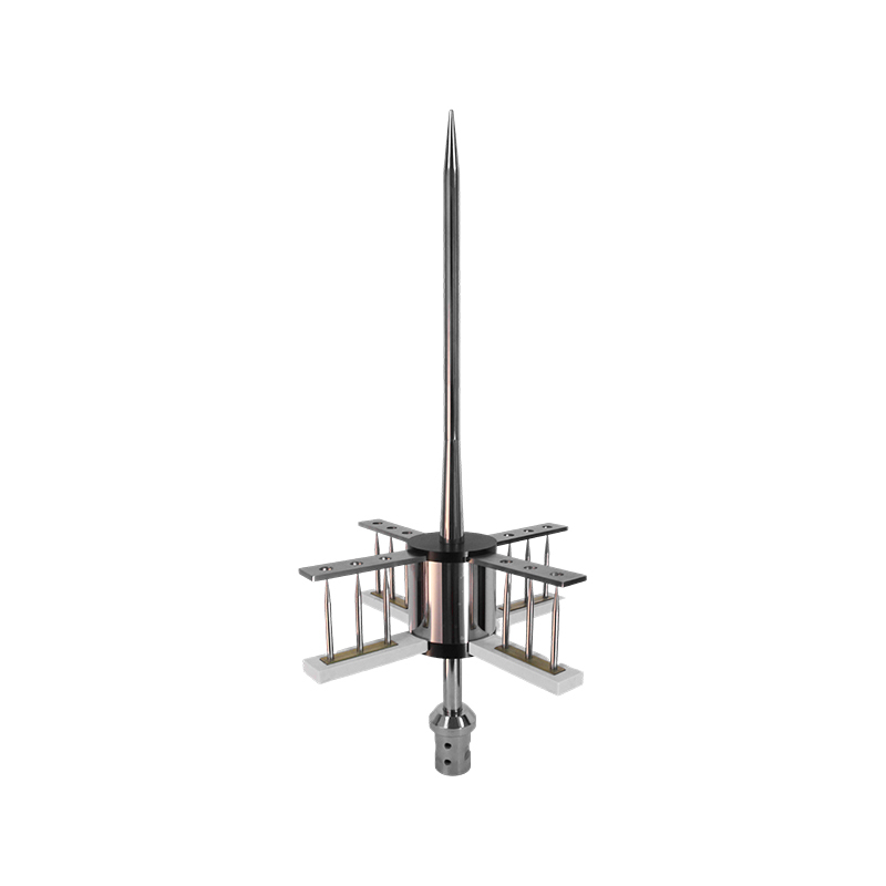 PDC 3.3–6.3 Early Discharge Lightning Rod for Building ProtectionThis active lightning terminal initiates early streamer emission to attract strikes safely. Shown after a discussion of corrosion-resistant transitions, it suits buildings requiring a reliable, low-maintenance air termination.View Product →
The Down Conductor Must Be a Continuous Low-Impedance Path
After the rod attaches, the down conductor is the first component that has to manage the lightning current. It should take the straightest practical route to the ground electrode, avoid sharp bends and loops, and be firmly fixed to the structure. Sharp bends increase the chance of side flashing and create extra inductance at high frequency. A conductor that is laid along a metal facade or close to internal equipment can also transfer energy into the building, so separation distance and bonding need to be considered.
Every junction on the down conductor is a potential failure point. Exothermic welding, proper clamps, and corrosion-resistant lugs are used to keep the connection stable. Mechanical clamps are convenient for maintenance, but they must be torqued correctly and inspected regularly because loose contact under impulse current can cause arcing.
The Grounding Half Determines Where the Current Ends Up
Lightning current cannot be stored or blocked; it must enter the soil. The ground electrode system needs enough surface area in contact with earth to let the current spread quickly and to limit the potential rise of the structure. A single copper-clad steel rod is often the starting point, but the required number, length, and spacing of rods depend on soil resistivity, moisture, and the owner's specification.
Engineering targets commonly fall between 5 and 10 ohms for many building and telecom grounding systems, while substation and high-risk sites may require lower values. There is no universal number; resistivity testing on site is the correct way to decide.
In poor soil, several rods in parallel or longer rods can help. The same earthing network should also bond metal building services, equipment enclosures, and the lightning down conductor to avoid dangerous potential differences.
When comparing electrode options, important factors include the corrosion rate of the rod material, the mechanical strength for driving into hard soil, and the method of connecting the down conductor. The grounding material selection guide explains the differences between copper-clad steel and solid copper in practical terms.
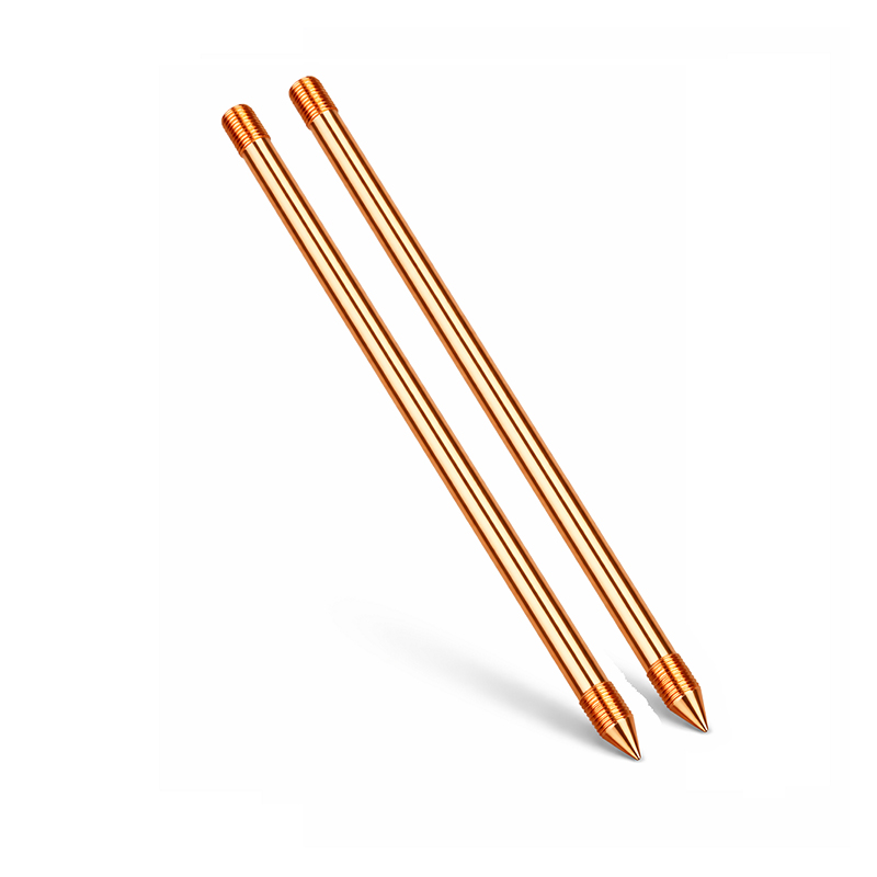 Copper-Clad Steel Ground Rod for Durable Earthing ElectrodesThis rod balances conductivity and mechanical strength for soil installation. Placed in a guide on electrode selection, it addresses corrosion and driving performance, making it a practical grounding choice.View Product →
Welded Connections Change the Weakest Point
An earthing network is only as reliable as its poorest connection. Bolted clamps can loosen during thermal cycling, corrode over time, and develop high resistance that forces current to flash across the gap. Exothermic welding uses a copper-based reaction inside a graphite mold to fuse conductors into one solid mass. The resulting connection is not dependent on surface pressure and will not relax after the mold is removed.
The welding process is used for common grounding joints, including cable-to-cable, cable-to-copper bar, cable-to-pipe, cable-to-steel plate, and multi-conductor-to-ground-rod nodes. For example, a vertical T-type connection can bring several horizontal tapes into one ground rod, and a cross-type connection can collect conductors from four directions.
- Welded joints maintain low resistance over their service life.
- They handle repeated lightning impulses without loosening.
- They eliminate the need for frequent torque checks on buried connections.
- They allow complex geometries that clamps cannot easily create.
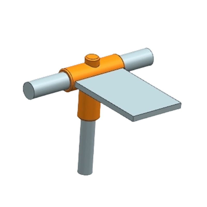 DW5 Vertical T-Type Welding Mold for Multi-Conductor Ground Rod JointsThis graphite mold creates a three-way vertical connection, merging copper tape, cable, or steel rod into one ground rod. Referenced after welding-process notes, it simplifies complex grounding nodes efficiently.View Product →
Inspection and Testing Keep the System Honest
Even a well-designed lightning rod system can degrade. Rods can be struck physically, connections can corrode in aggressive soil, and ground resistance can change as moisture moves through the soil. An annual visual inspection of air terminals and down conductors is a reasonable baseline, and a full earth resistance test after major storms is prudent.
Typical checks include rod and conductor tightness, signs of burning or pitting, and the condition of exothermic welds. If a welded joint looks cracked or porous, it should be redone before the next storm season.
A Lightning Rod Is Only One Half of the Protection Story
The final conclusion is simple. A lightning rod is effective when it is part of a complete vertical circuit: an air terminal that provides a dependable strike point, a down conductor that keeps the current away from occupants and equipment, welded or properly clamped connections that cannot silently fail, and grounding electrodes that can dissipate the current into the soil.
No single component can substitute for the rest. When you compare hardware for a new build or a retrofit, evaluate the rod, the conductor, the connectors, and the ground electrode as a set. The complete lightning protection product range on this site is a practical starting point because it covers the full path from air terminal to grounding accessories.
PREV: How Does a Ground Work? Key Components and Exothermic Connections for Safety
NEXT: Copper Stranded Wire: Construction, Finishes, and Grounding Selection Guide
Contact Us
Your email address will not be published. Required field are marked*
News
-
-
An electrical grounding system works by creating a dedicated, low-impedance pat...
Read More -
A ground clamp is the mechanical connection between an earthing conductor and a...
Read More -
Yes, lightning rods work — but not in the way many people imagine. They do not ...
Read More -
Recently, as global requirements for power safety and lightning protection groun...
Read More -
Copper-Clad Steel Rod: Definition and Manufacturing Process Analysis What is a C...
Read More

The company is committed to in-depth research in the field of
grounding and large-scale manufacturing of products. It is a
comprehensive technology enterprise integrating R&D,
manufacturing and technical services. It is a high-quality
supplier for many domestic first-line engineering construction
companies.
- Contact Information
-
- TEL
- +86-575 8930 2616
- +86-130 6788 7328
- Address
- No. 55, Gaoxiang Road, Shengzhou City, Shaoxing City, Zhejiang Province, China
- Grace Wang
- E-mail: [email protected]
- Phone:+86 135 8735 6239
- WhatApp: +86 135 8735 6239
- WeChat: +86 135 8735 6239
- Lucy Xu
- E-mail: [email protected]
- Phone:+86 139 0585 3744
- WhatApp: +86 139 0585 3744
- WeChat: +86 139 0585 3744
- April Zhang
- E-mail: [email protected]
- Phone:+86 139 0585 4994
- WhatApp: +86 139 0585 4994
- WeChat: +86 139 0585 4994

