


 English
  中文简体
中文简体 Every building, substation and telecom tower quietly depends on metal buried in...
Read More

Home · News · Industry News · How Does Grounding Work? A Practical Guide to Earthing and Fault Current Paths
Industry News
How Does Grounding Work? A Practical Guide to Earthing and Fault Current Paths
2026-10-14Content
- 1 How Grounding Works in Principle
- 2 The Fault Path, Step by Step
- 3 Grounding, Earthing and Bonding: Sorting Out the Terms
- 4 What a Grounding System Is Made Of
- 5 Connections Decide Whether Grounding Holds Up
- 6 Above Ground: Clamps, Bonding and Lightning Protection
- 7 Ground Resistance and Material Choices
- 8 Keeping a Grounding System Working
How does grounding work? Set the jargon aside and it comes down to one simple idea: give electricity a controlled, low-resistance route into the earth, and keep every metal surface a person can touch at close to the same voltage. That single principle covers a small control cabinet, a substation ground grid, and the base of a communications tower. What changes is scale, soil, and the hardware you choose.
One clarification before we go further. In this article grounding means electrical earthing, the kind used in power distribution, buildings and industrial equipment, not the wellness practice of standing barefoot on grass. The physics overlaps, but the standards and the hardware do not.
Below we walk through what actually happens during a fault, why the earth is not a drain that quietly swallows current, and where grounding systems most often go wrong.
How Grounding Works in Principle
Soil conducts electricity, but not very well on its own. Moisture and dissolved minerals do the work, which is why a rod driven into wet clay behaves very differently from the same rod in dry sand. When current enters the earth through an electrode, it spreads outward in shells, and most of the resistance sits in the first short distance around the electrode. That is the most useful fact to hold onto: because resistance is concentrated so close to the rod, driving it deeper helps less than most people expect.
From the system's point of view, a grounding connection does three things at once.
- It fixes a reference. One point of the supply, usually the transformer neutral, is tied to earth, so system voltage stays predictable instead of floating.
- It opens a path for fault current. When insulation fails and a live conductor touches metal, grounding gives that current somewhere to go, which is what allows a breaker or fuse to operate.
- It diverts surges. Lightning and static charges travel to earth instead of through insulation or through people.
Only one of those three is about a device tripping. Grounding also sets the voltage baseline for everything connected to it, and that baseline matters just as much.
The Fault Path, Step by Step
The sequence is worth spelling out, because it explains why a high-resistance grounding system is dangerous even when nothing looks wrong.
- A live conductor touches a metal enclosure, a conduit, or a frame.
- Current flows through that metal into the equipment grounding conductor.
- It arrives at the panel ground bus and leaves along the grounding electrode conductor.
- Part of the current spreads into the earth; the rest travels through the soil and back to the source through the utility's grounded neutral.
- Because the loop has low impedance, the current is large and the overcurrent device opens in milliseconds.
- The voltage on the enclosure falls back to a safe level.
Step four is the one people miss. The earth is not the end of the circuit, it is half of it. Current has to return to its source. If the return path is poor, fault current stays small, the breaker may not trip at all, and the metal someone is touching stays energized. That is why grounding and overcurrent protection have to be designed as one system.
Grounding, Earthing and Bonding: Sorting Out the Terms
The words get used interchangeably in conversation, but they describe different jobs. Keeping them separate makes troubleshooting far easier.
| Term | What it connects | What it does |
|---|---|---|
| System grounding | One point of the supply, usually the neutral, to earth | Holds system voltage at a defined level and limits overvoltage |
| Equipment grounding | Enclosures, conduit and frames to the grounding conductor | Carries fault current so protective devices trip quickly |
| Bonding | Metal parts to each other | Keeps touch voltages near zero between adjacent surfaces |
| Ground electrode | Rods, plates or grids to the soil | Provides the physical contact with earth |
What a Grounding System Is Made Of
A working system has four layers stacked on top of each other.
- The electrode: driven rods, buried plates, rings, or the reinforcing steel in a foundation.
- The grounding electrode conductor: the wire that ties the electrode to the service or the ground bus.
- Interior conductors and busbars: bonding jumpers, ground bars, cabinet terminals.
- Connections: the joints that hold the whole chain together.
Rods are usually the most economical way to reach undisturbed soil, and a typical rod is at least 8 feet (2.4 m) long so that its full length sits below the frost line and in permanent moisture.
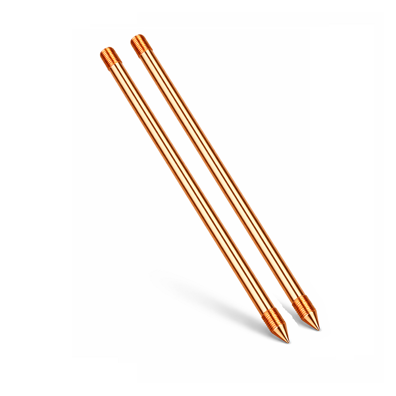 Copper-Clad Steel Grounding Rod for Power SystemsA copper-clad steel rod for grounding systems, combining copper conductivity with steel strength for durable, corrosion-resistant electrodes in undisturbed soil.View Product →
Where soil is shallow or rocky, plates, ring electrodes or chemical electrodes take over. In new construction, the concrete-encased electrode cast into the footing often does most of the work for the life of the building.
Connections Decide Whether Grounding Holds Up
A grounding system is only as good as its joints. A buried joint cannot be inspected next year and cannot be retightened, so the choice between welding and clamping matters more underground than anywhere else.
- Exothermic welding: a graphite mold holds the conductors while a charge of welding powder reacts and fuses them into a molecular bond. There is no contact resistance to loosen and no dissimilar-metal interface to corrode.
- Mechanical clamps and compression lugs: serviceable and quick to install, which makes them a good fit above ground. They depend on correct torque, and they can work loose under vibration or degrade in aggressive soil.
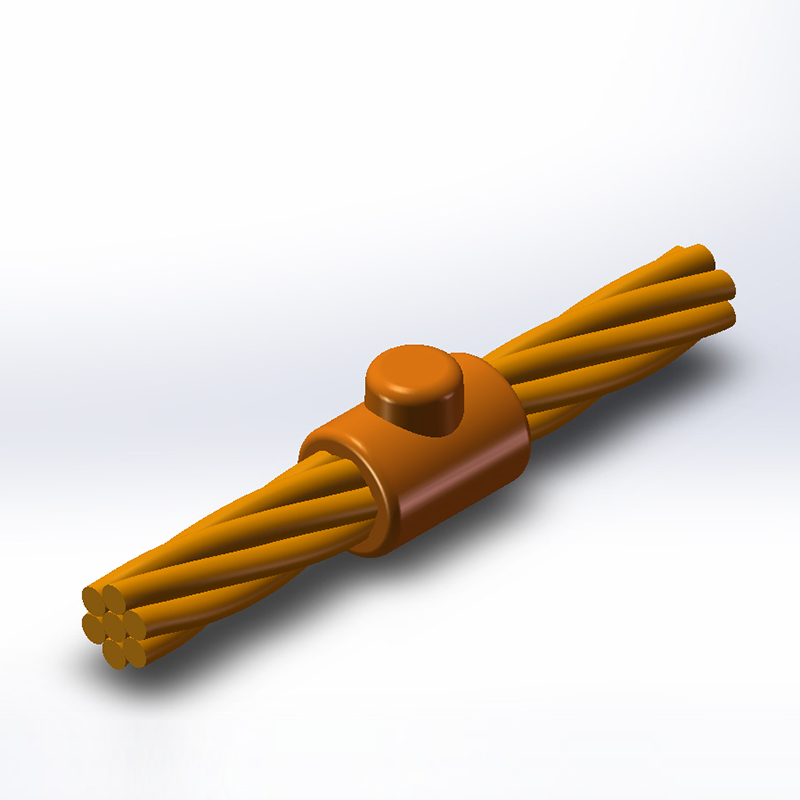 AW1 Cable-to-Cable Exothermic Welding MoldA graphite mold for straight cable-to-cable exothermic joints, producing repeatable low-resistance bonds where buried grounding connections cannot be retightened.View Product →
Molds are matched to the joint, not to the project: cable to cable, cable to bar, bar to bar, rod to rod, plus horizontal T, vertical T and cross configurations for branch connections and networks. Using the right mold for the conductor combination is what keeps the weld repeatable from the first joint to the five hundredth.
Above Ground: Clamps, Bonding and Lightning Protection
Above the soil line, most of the work is bonding. Bonding jumpers tie enclosures, pipes, cable trays and structural steel together so that no two surfaces reach very different voltages during a fault or a surge. Clamps do the mechanical half of that job, and they are the part maintenance crews actually see and touch.
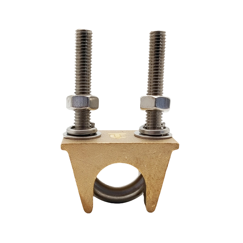 Custom Brass U-Type Grounding ClampA brass U-clamp for bonding conductors and grounding bodies, sized for Φ5–50 mm and offering durable, corrosion-resistant connections in above-grade grounding work.View Product →
At the top of the installation sits lightning protection: an air terminal or rod, a down conductor, and a low-impedance route into the same grounding network that protects the electrical system. A lightning rod without a solid grounding path is decoration, not protection.
Ground Resistance and Material Choices
Resistance to earth is the number you measure to confirm the system works. It depends on soil resistivity, the surface area of the electrode in contact with soil, depth, moisture, temperature, and how many electrodes you drive. Many specifications ask for 5 ohms or less on commercial and industrial sites, while some residential work accepts 25 ohms. Either way, the meaningful question is whether the protective device will actually operate.
Material selection follows the soil. Copper performs well almost everywhere but is costly and a target for theft. Copper-clad steel pairs a steel core with a copper skin, so it drives cleanly and resists corrosion while being far less attractive to scrap thieves. Hot-dip galvanized steel is a practical choice for larger grids where budget drives the decision, though it is a poor match for acidic or chloride-rich ground. We put together a comparison of copper and copper-clad steel for grounding work if you are weighing the two for a specific site.
Keeping a Grounding System Working
Grounding is not a one-time installation. Resistance shifts with the seasons, and connections corrode quietly. A sensible routine is to measure resistance at least once a year, inspect test wells and accessible joints, retorque the mechanical connections you can reach, and re-test after any nearby excavation or soil work. A reading that has crept upward two years in a row is telling you something.
Grounding rewards attention to detail. The concept is simple, but the outcome depends on the right electrode for the soil, conductors sized to the fault current, and connections that are still solid after thirty years underground.
That is the part of the work we handle every day. Our team supplies exothermic welding powder, molds and toolkits, copper-clad steel and copper conductors, ground clamps, busbars and lightning rods, and we are glad to talk through mold selection or material matching on a real project. You can browse our grounding and lightning protection product range whenever you are ready to specify.
PREV: No previous article
NEXT: How Do Thunderstorms Form? The Science of Storm Development and Lightning Safety
Contact Us
Your email address will not be published. Required field are marked*
Categories
- Company News(1)
- Industry News(19)
News
-
-
“How does a lightning rod work?” is one of those questions that sounds simple u...
Read More -
An air terminal by itself does not protect a building. A lightning rod works on...
Read More -
An electrical grounding system works by creating a dedicated, low-impedance pat...
Read More -
Exothermic welding is a process that fuses two metal conductors into a single m...
Read More -
Thunderstorms are one of nature's most dramatic weather events. They can appear...
Read More

The company is committed to in-depth research in the field of
grounding and large-scale manufacturing of products. It is a
comprehensive technology enterprise integrating R&D,
manufacturing and technical services. It is a high-quality
supplier for many domestic first-line engineering construction
companies.
- Contact Information
-
- TEL
- +86-575 8930 2616
- +86-130 6788 7328
- Address
- No. 55, Gaoxiang Road, Shengzhou City, Shaoxing City, Zhejiang Province, China
- Grace Wang
- E-mail: [email protected]
- Phone:+86 135 8735 6239
- WhatApp: +86 135 8735 6239
- WeChat: +86 135 8735 6239
- Lucy Xu
- E-mail: [email protected]
- Phone:+86 139 0585 3744
- WhatApp: +86 139 0585 3744
- WeChat: +86 139 0585 3744
- April Zhang
- E-mail: [email protected]
- Phone:+86 139 0585 4994
- WhatApp: +86 139 0585 4994
- WeChat: +86 139 0585 4994

