


 English
  中文简体
中文简体 The three fundamental types of clamps are screw clamps, spring clamps, and togg...
Read More

Home · News · Industry News · What Is a Ground Clamp? Earthing Clamps & Fixing Clamps Explained for Safe Grounding
Industry News
What Is a Ground Clamp? Earthing Clamps & Fixing Clamps Explained for Safe Grounding
2026-08-14Content
A ground clamp is the mechanical connection between an earthing conductor and a ground rod, a structural member, or another part of the grounding system. The clamp is where the protective circuit is physically made, so a loose, corroded, or undersized clamp can raise the entire earthing resistance above the acceptable limit even when the electrodes and conductors themselves are faultless. The practical takeaway is straightforward: the right ground clamp depends on only a few variables — clamp type, base material, size range, and installation quality. Get those four right and the connection will stay stable for years; get one wrong and the clamp becomes the weakest point of the whole system.
What Is a Ground Clamp?
Ground clamp, grounding clamp, earthing clamp, and earth clamp all name the same family of fittings. An earthing clamp creates a secure mechanical and electrical joint between an earthing conductor and the electrode or structure it must connect to. Unlike a welded joint, the clamp can be removed, inspected, and retightened, which is why it is the standard choice for visible connections at grade level, inside earth pits, and on equipment.
The term "earthing fixing clamp" is used when the primary job is to fix, or secure, a conductor to a surface or structure while maintaining electrical continuity — for example, a bare copper conductor fixed to a wall, a copper tape run along a steel beam, or a stranded earth cable clipped to a bracket. Many fixing clamps do double duty: they support the conductor and carry current at the same time.
One distinction is worth making early. In arc welding, the "earth clamp" is the return-current clamp attached to the workpiece, and that product family is different from the earthing and fixing clamps described here. A grounding-system earthing clamp connects conductors to electrodes and structures; it is part of the protective earthing circuit, not the welding circuit.
The points where clamps appear in a typical earthing system are consistent:
- down conductor to driven ground rod
- copper tape or flat bar to structural steel
- equipment earth lead to a busbar or earth pit
- test link between the earth grid and an above-grade riser
- temporary earth connection during maintenance work
Main Types of Earthing Clamps and Fixing Clamps
Manufacturers name clamps by body geometry. The five types that appear most often in grounding work are U-type, V-type, C-type, cross clamps, and tower wire clamps.
U-Type Ground Clamp
The U-type clamp is the default rod-to-conductor fitting. A U-shaped bolt wraps around the ground rod, and tightening the nut pulls the conductor down against the rod surface. It works with bare copper, copper-clad steel, and galvanized conductors on round rods. Sizing is matched to rod diameter (typically 14 mm, 16 mm, 17.5 mm, 5/8 in, or 3/4 in) and to the conductor cross-section, so a clamp that grips a 25 mm² cable will not safely accept a 95 mm² cable even on the same rod. The U-type ground clamp is the first fitting to specify when a down conductor terminates at a driven rod.
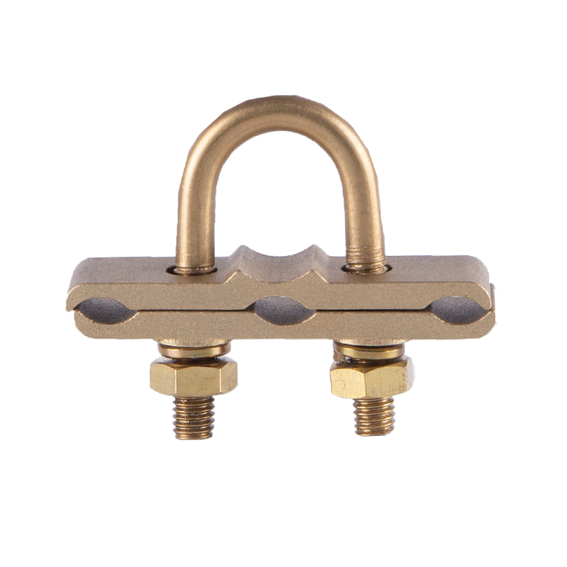 Custom U-Type Ground Clamp Manufacturers, SuppliersShaoxing Sweld Electric Co., Ltd. is U-Type Ground Clamp manufacturers and U-Type Ground Clamp suppliers in China, we custom U-Type Groun...View Product →
V-Type Ground Clamp
The V-type clamp seats a round conductor in a V-shaped groove machined into the clamp body. As the clamp is tightened against the rod, the groove presses the conductor into firm line contact across its full width. This design suits stranded and solid round conductors from roughly 16 mm² to 120 mm² and is common in earth pits where height is limited. A V-type ground clamp provides a low-profile connection with a larger contact area than a single-point bolt.
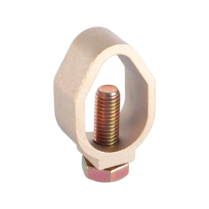 Custom V-Type Ground Clamp Manufacturers, SuppliersShaoxing Sweld Electric Co., Ltd. is V-Type Ground Clamp manufacturers and V-Type Ground Clamp suppliers in China, we custom V-Type Groun...View Product →
C-Type Cable Clamp
A C-type cable clamp fixes a cable to a flat surface such as a wall, beam, or enclosure. The clamp opens like a C, the cable is placed inside, and the fixing screws close the body around the conductor. When the body is conductive, it also bonds the cable to the supporting structure. This makes C-type cable clamps a practical fixing and bonding solution for vertical down-runs, cable trays, and terminations against steel columns.
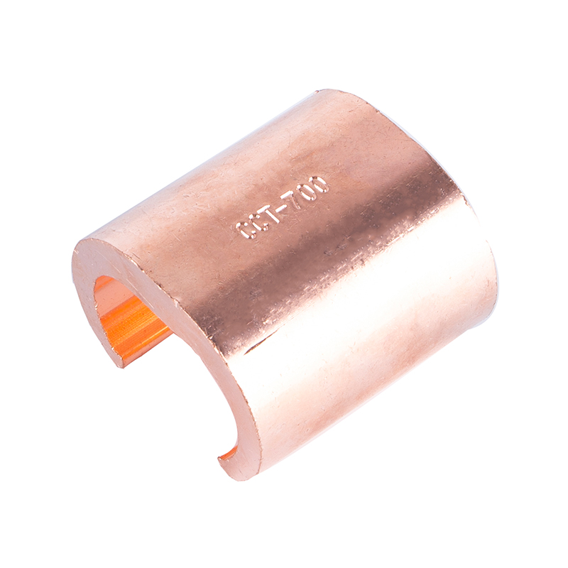 Custom C-Type Cable Clamp Manufacturers, SuppliersShaoxing Sweld Electric Co., Ltd. is C-Type Cable Clamp manufacturers and C-Type Cable Clamp suppliers in China, we custom C-Type Cable C...View Product →
Cross Clamp
A cross clamp connects two conductors that cross at right angles. It is used where a branch conductor meets a main earth run or where grid conductors intersect, avoiding the need to cut and weld the main conductor to form a tee joint. The clamp body holds each conductor in its own seat, which keeps the grid continuous and lets either conductor be released for testing.
Tower Wire Clamp
Tower wire clamps are built for lattice towers and poles. They attach down conductors, overhead shield wire, or bare stranded earth wire to tower legs with a bolted body designed to survive wind-driven vibration and repeated thermal cycling. In this application mechanical strength is as important as electrical contact, because a conductor that works loose at height can create an energised part in an unprotected area.
| Clamp type | Connection | Typical application |
|---|---|---|
| U-type | Conductor to round ground rod | Down conductor to electrode at grade level |
| V-type | Round conductor to rod or pipe | Low-profile earth pit connection |
| C-type | Cable to flat surface or structure | Cable fixing and structural bonding |
| Cross clamp | Two crossing conductors | Grid intersections and branch taps |
| Tower wire clamp | Conductor or shield wire to tower leg | Transmission and communication towers |
Mechanical Clamps vs. Exothermic Welding
The first engineering decision at any connection point is whether to use a mechanical clamp or a welded joint. Exothermic welding creates a permanent molecular bond between copper conductors or between copper and steel. There is no separable interface, so there is no added contact resistance, no bolt to retighten, and no moisture trap. That is why underground earth grids and direct-buried connections are almost always welded, and it is the same reason the exothermic welding powder used in lightning protection and grounding work has become the default for permanent conductor connections.
Mechanical clamps cover the areas where welding is impractical or unwanted. Clamp connections are visible and inspectable, they allow disconnection for testing, and they are the only practical option when the structure cannot tolerate heat or when a new conductor must be attached to an existing system without interrupting service. Earthing clamps therefore dominate above-grade terminations, earth pits, equipment bonding, and temporary earths.
Resistance behaviour completes the picture. A properly installed clamp starts with low contact resistance, but its long-term value depends on surface preparation, torque, and environment. A welded joint has no interface to degrade, so its resistance stays essentially constant over the service life of the conductor. For buried or permanent connections, welding is the safer long-term choice; for accessible serviceable connections, a clamp is the smarter one.
Materials, Corrosion, and Galvanic Compatibility
The metal of the clamp body determines how long the connection survives in service.
Copper, Brass, or Galvanized Steel?
Copper alloy clamps are standard for copper and copper-clad steel conductors. Hot-dip galvanized steel clamps are used with galvanized rods and structural steel. The trouble starts when dissimilar metals are paired: a copper clamp on a galvanized rod in wet soil forms a galvanic couple that consumes the zinc coating around the contact point and leaves the steel to rust. Tin-plated copper clamps reduce this effect and are the safer option wherever the clamp will be buried or exposed to rain. The material logic here follows the same thinking as the copper-clad steel grounding material selection guide: match the clamp to the electrode or conductor it touches, and choose a plated version where moisture is constant.
Brass clamps are chosen indoors and in marine environments where corrosion resistance matters more than bulk conductivity. Stainless steel clamps are specified for food, pharmaceutical, and washdown installations. In every case the contact face should be clean and free of sharp edges that could cut conductor strands.
The Hardware Is Part of the Connection
The bolt, nut, and washer often fail before the clamp body does. Ordinary zinc-plated hardware corrodes quickly in ground contact, while hot-dip galvanized or stainless steel hardware lasts for the service life of the installation. Torque matters just as much. An under-torqued clamp lets the conductor move; an over-torqued clamp deforms the strands and creates a stress point. This is why installation instructions specify a clean contact surface, an anti-oxidation compound on copper joints, and a torque value rather than an instruction to simply tighten firmly.
What to Check Before You Buy or Install a Ground Clamp
Sizing
A clamp is correct only if it fits both the conductor and the electrode. Check three numbers: conductor cross-section (for example 25 mm² or 70 mm²), conductor construction (stranded or solid), and rod or pipe diameter. A clamp whose body accepts the rod but whose saddle is too small for the conductor either will not close fully or will crush the strands.
Installation Sequence
Clean the rod surface where the clamp sits, remove paint or powder coating from structural steel, apply an anti-oxidation compound, place the conductor so it is fully captured in the seat, tighten to the specified torque, and confirm the conductor has not been deformed. These steps take minutes, but they decide the measured resistance of the connection.
Procurement Checklist
The practical questions to ask before ordering a batch of clamps are consistent across suppliers:
- confirm that the conductor range and rod diameter printed on the clamp match the project specification
- specify a base material compatible with the conductor and electrode
- choose tin-plated or stainless hardware for outdoor and buried use
- verify whether the clamp is rated for above-grade or below-grade service
- check that the contact face has no burrs or sharp edges
- select a clamp that allows a test lead to be attached where routine testing is planned
The Bottom Line
A ground clamp completes the earthing circuit. U-type and V-type clamps connect conductors to rods, C-type clamps fix cables to structures, cross clamps tie crossing conductors, and tower clamps hold conductors on towers. The same fitting may be called a ground clamp, earthing clamp, or fixing clamp depending on the regional standard, but the engineering role is identical: a low-resistance, mechanically stable connection that can be inspected and maintained.
Shaoxing Sweld Electric Co., Ltd. is a grounding and lightning protection materials supplier covering the full chain around that connection — earthing clamps, exothermic welding consumables, copper-clad steel, galvanized steel, and copper conductors. When the clamp type, material, size, and installation are chosen together, the grounding system performs as designed, and the small fitting at the joint stops being the weakest link.
PREV: Do Lightning Rods Really Work? The Truth About How They Protect Structures
NEXT: What Are the Three Types of Clamps? From Standard Mechanics to Mold Clamps & Exothermic Welding Solutions
Contact Us
Your email address will not be published. Required field are marked*
Categories
- Company News(1)
- Industry News(19)
News
-
-
Exothermic welding is a process that fuses two metal conductors into a single m...
Read More -
Copper-Clad Steel Rod: Definition and Manufacturing Process Analysis What is a C...
Read More -
An air terminal by itself does not protect a building. A lightning rod works on...
Read More -
How does grounding work? Set the jargon aside and it comes down to one simple i...
Read More -
An electrical grounding system works by creating a dedicated, low-impedance pat...
Read More

The company is committed to in-depth research in the field of
grounding and large-scale manufacturing of products. It is a
comprehensive technology enterprise integrating R&D,
manufacturing and technical services. It is a high-quality
supplier for many domestic first-line engineering construction
companies.
- Contact Information
-
- TEL
- +86-575 8930 2616
- +86-130 6788 7328
- Address
- No. 55, Gaoxiang Road, Shengzhou City, Shaoxing City, Zhejiang Province, China
- Grace Wang
- E-mail: [email protected]
- Phone:+86 135 8735 6239
- WhatApp: +86 135 8735 6239
- WeChat: +86 135 8735 6239
- Lucy Xu
- E-mail: [email protected]
- Phone:+86 139 0585 3744
- WhatApp: +86 139 0585 3744
- WeChat: +86 139 0585 3744
- April Zhang
- E-mail: [email protected]
- Phone:+86 139 0585 4994
- WhatApp: +86 139 0585 4994
- WeChat: +86 139 0585 4994

